Introduction
This is the first in a series of Power Supply articles I am working on. Each will evolve in complexity, function, and practical application. Before starting power supply experiments, review and follow electrical safety procedures. Here is a short article I wrote on Electrical Safety.
Given
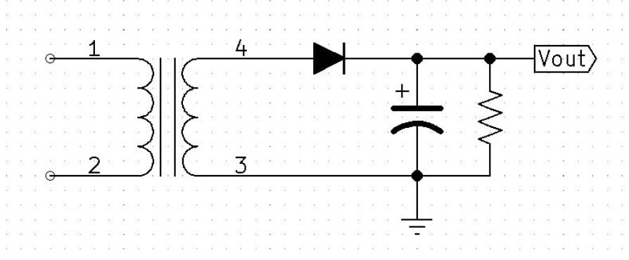
Given: Vpri = 120v 60Hz, Turns ratio = 4:1, C1 = 10uF, RL = 10K Ohms
Calculate Primary Voltage
Start by converting the primary RMS voltage to Peak voltage.
Primary Voltage Waveform
Calculate Secondary Voltage
Find the Secondary Peak Voltage.
Secondary Voltage Waveform
Find Unfiltered Output Voltage
Imagine the circuit without the filter capacitor. During the positive cycle of the secondary voltage, the diode will be forward-biased and will allow current to flow. During the negative cycle of the secondary voltage, the diode will be reverse biased and no current will flow through the resistor.
Unfiltered Half-Wave Voltage Waveform
Add Filtering
Calculate what the capacitor discharge voltage will be. When the diode is forward biased, the capacitor will immediately charge to 41.733V (Vsecondary – Vdiode). The capacitor will have one cycle worth of time to discharge, this is a half-wave rectifier, the time will be 1/60hz or 16.667ms. Because we are looking for a discharge voltage, Vfinal will be equal to zero volts in our formula and Vinitial will be equal to 41.733V.
$$VC_{max}=41.733V$$
Filtered Output Waveform Voltage
Vrpp & VDC
V ripple peak to peak is found by subtracting Vmax from Vmin & VDC is the average voltage.
VDC Waveform Voltage represented in blue
Vrms & %ripple
Vrms is the RMS equivalent of the ripple voltage and %ripple is a ratio of Vrms to VDC, describing how well the output DC is filtered.
Notice that the ripple waveform is more triangular than sinusoidal. This is why we use the square root of 3 rather than 2.