This article is included in the ISTEM 2023 Series
Basic Regulation Circuit:
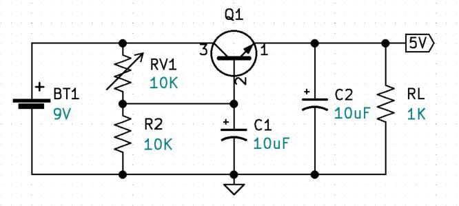
Using a 9V battery we can safely experiment with a basic voltage regulator.
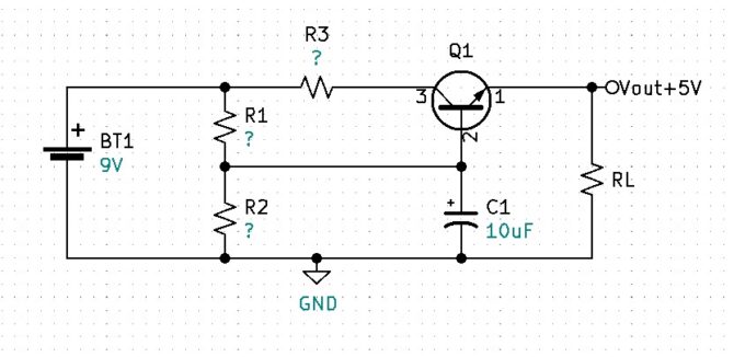
First Challenge:
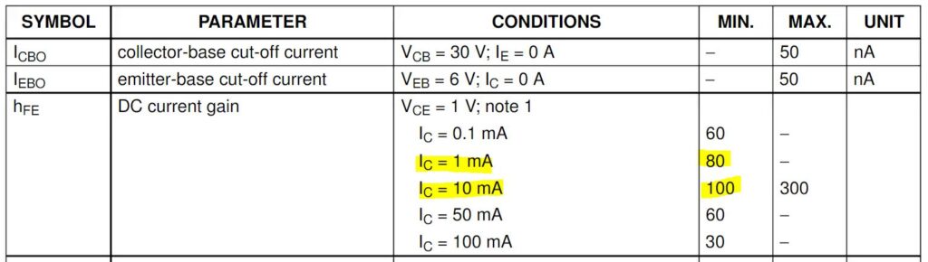
Calculate and find the resistor values for the above circuit to produce a regulated 5V output with a max current of 5mA. Notice that the data sheet excerpt has a minimum beta of 80 at 1mA and a minimum beta of 100 at 10mA, because we are designing our circuit to operate at 5mA we will assume a minimum beta of 90 for our 2N3904 Q1.
Solution for First Challenge:
Find the maximum base current IB for Q1.
Make IR2, at a minimum, 10 x IBmax.
Find VR2 using Kirchhoff’s Voltage Law.
Find approximate R2 value using Ohm’s Law.
Round the R2 value down to the next standard value.
$$R_{2}=10K\Omega$$
Recalculate IR2 using Ohm’s Law.
Find IR1 using Kirchhoff’s Current Law.
Find VR1 using Kirchhoff’s Voltage Law.
Calculate R1 using Ohm’s Law.
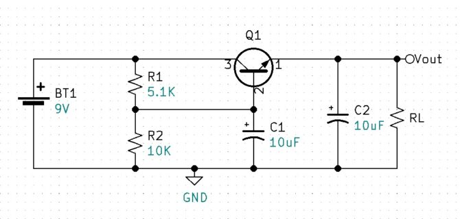
C1 & C2 filter capacitors
RL minimum
If your circuit is like mine, your output was not exactly 5V. This may be due to a higher-than-calculated battery voltage or a resistor value that is slightly off. One way we can make the output adjustable is to replace R1 with a variable resistor. Initially, set RV1 to 5K ohms, power up the regulator then adjust RV1 for a perfect 5V output.
Adjustable Circuit
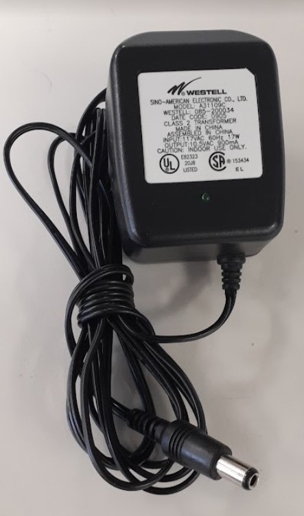
Let’s say we want to design a circuit that has the ability to accept a variety of input voltages instead of just 9V. How might we deal with a range of input voltages and still maintain a regulated output of 5V? If you are like me, you have a box full of salvaged electronic components. I have one dedicated to wall AC to DC power adapters. These wall adapters, sometimes referred to as “wall warts” take care of voltage rectification for us by internally converting the 120Vrms AC voltage to a fixed DC voltage. Typically, the output voltage and current specifications are written on the adapter. The adapter shown in the image is listed as having an output of 10.5V that can supply up to 900 milliamps of current. Let’s say I also have a wall adapter that has a 12V output and a third that has a 20V output.
Can we design a single circuit that will accommodate each of those inputs while still providing a regulated 5V output? By replacing R2 in our original circuit with a Zener diode we can achieve regulation throughout a range of input voltages.
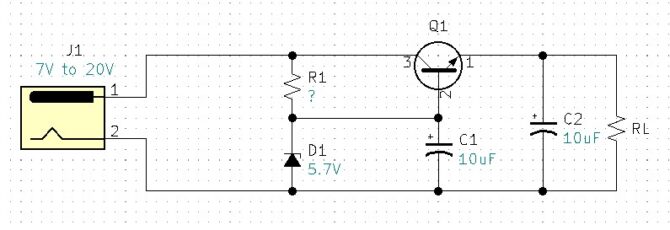
Ideally, D1 would be a 5.7V Zener, I had on hand a 1N5233 6V Zener diode. Concerning Zener diodes, there are two important specifications we need to know, the maximum Zener current (IZM) and the minimum Zener current known as knee current (IZK).
Similar to how we used diodes in our AC-to-DC voltage rectification circuit, we can use diodes to provide DC polarity correction.
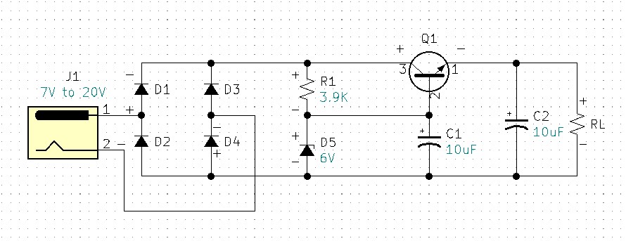
For this example, I am using 1N4001 general-purpose diodes for D1-D4.
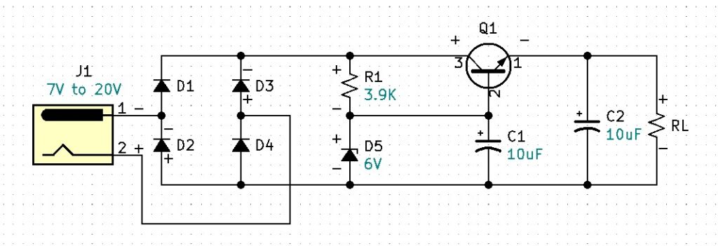
Observe where J1 pin 1 is positive with respect to pin 2, diodes D1 and D4 are forward biased and diodes D2 and D3 are reverse biased. The result is the rest of the circuit is properly biased. Observe where J1 pin 1 is negative with respect to pin 2, diodes D2 and D3 are forward biased and diodes D1 and D4 are reverse biased. The result is the rest of the circuit is again properly biased. Therefore, the circuit is now adapted to receive either positive, negative, or unknown voltage polarities. This circuit makes virtually all of our salvaged wall adapters useable. I assembled and tested the circuit with +20VDC. Using a 1K ohm load I measured an output of +5.08VDC. I also tested with -20VDC input and measured +5.08VDC at the output.
What happens to this circuit if the output is shorted?
The answer is the transistor will exceed its power specifications and destroy itself. None of the previous circuits have had any current limiting protection. If you are building a dedicated circuit that will be deployed with a fixed load and a fixed input voltage, and you can guarantee that the output will never be shorted, the previous circuits will work fine. However, adding current limiting circuit protection is always a good idea.
What is a simple way to apply current limiting protection to our circuit?
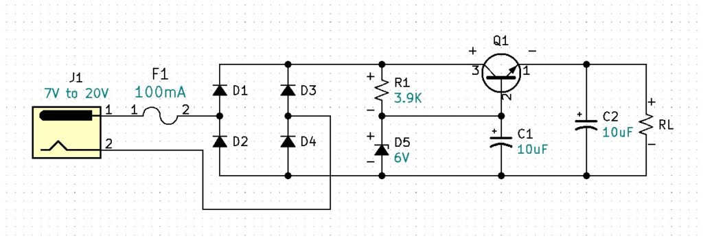
A fuse can provide basic current-limiting protection for your circuit. To determine the proper fuse value, we need to consider all the parts that will be affected when the output is shorted or overloaded. We can see that Q1 and the polarity correction diodes are in the direct path between the voltage source and the output. Additionally, we should consider the output rating on the AC/DC wall adapter. All wall adapters will be rated differently. My wall wart is rated at 900mA. According to the datasheet, the 1N4001 diodes are rated at a maximum forward current of 1A. The 2N3904 BJT is rated at an absolute maximum forward DC current of 200mA. So, for this circuit, we will need to protect the weakest link which is the 2N3904 BJT at 200mA. If your wall adapter is rated less than 200mA, your fuse choice would be based on that current. Because 200mA is the absolute maximum, we will want to guarantee that the current will stay well below 200mA. Our circuit is designed to run at 5mA so our fuse will need to be larger than 5mA and well below 200mA. An appropriate fuse for the circuit is a slow blow 100mA or 0.1A fuse.
Now that we are fused at 100mA, let’s consider what circuit adjustments we may need to accommodate the higher current.
We know the transistor Q1 can handle a forward current of 100mA. We need to recalculate the transistor’s power with a load current of 100mA and determine if the power at Q1 is still in its specification.
ReCalculating Circuit Values for 100mA
$$RL_{100mA}=\frac{V_{RL}}{I_{RL}}$$
$$RL_{100mA}=\frac{5V}{100mA}$$
$$RL_{100mA}=50\Omega$$
$$VCE_{max}=VIN_{max}-V_{RL}$$
$$VCE_{max}=20V-5V$$
$$VCE_{max}=15V$$
$$IC_{max}=F1$$
$$IC_{max}=100mA$$
$$PQ1_{100mA}=VCE_{max}\times IC_{max}$$
$$PQ1_{100mA}=15V\times 100mA$$
$$PQ1_{100mA}=1.5W$$
1.5 watts is too high for the 2N3904. There are two ways we can deal with this problem. The first is to do a power split by adding, a parasitic power resistor in series with the collector of the transistor. The second option is to use a Darlington Pair.
First, let’s take a look at the parasitic power resistor.
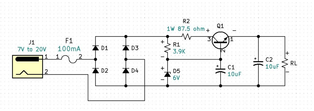
Power Split
$$PQ1_{max}=625mW$$
$$PR2_{max}=P_{R2+PQ1}-PQ1_{max}$$
$$PR2_{max}=1.5W-625mW$$
$$PR2_{max}=875mW$$
VR2
$$VR2=\frac{PR2_{max}}{IC_{max}}$$
$$VR2=\frac{875mW}{100mA}$$
$$VR2=87.5V$$
R2
$$R2=\frac{VR2_{max}}{IC_{max}}$$
$$R2=\frac{8.75V}{100mA}$$
$$R2=87.5\Omega$$
The parasitic R2 circuit will work fine when the load is 5mA. However, now that we can operate up to 100mA without damaging any of the parts, a problem has been introduced via R2. Can you spot the problem?
If we operate our output at 99mA, what is the required input voltage?
Calculate the required input voltage when the output is running a 99mA load.
$$V_{R2}=I_{R2}\times R2$$
$$V_{R2}=99mA\times 87.5\Omega$$
$$V_{R2}=8.663V$$
$$V_{in}=V_{D1}+V_{D4} +V_{R2}+VCE_{min}+V_{RL}$$
$$V_{in}=0.7V+0.7V +8.663V+2V+5V$$
$$V_{in}=17.063V$$
A Vin requirement of 17V for our circuit is not practical. Using this method would severely limit the flexibility of this circuit. A preferable method is to use a Darlington Pair with a higher-powered transistor.
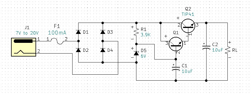
The Darlington Pair Q1 & Q2 is a current multiplier. The power transistor TIP 41 is able to handle more power than the 2N3904. A question you may be thinking is why not omit the 2N3904 Q1 transistor and replace it with the power transistor TIP41? The answer is, power transistors have a much lower beta or hfe than general-purpose transistors. Therefore, our base current would go up significantly and we would also need to raise our zener current (keeping it 10X larger than the base current). We would also need to verify our IZ current is below IZM. Additionally, the increase in IZ would require a recalculation of the R1 value to accommodate the increases in current. This would negatively impact our efficiency, we don’t want more quiescent current to go directly to ground through the Zener. Imagine if your power supply was battery-powered, an increase in IZ would discharge your battery faster. By using the Darlington, we can keep the current through the Zener significantly lower, while increasing the current through the load.
With the Darlington Pair, if the circuit was run at its maximum current of 100mA, what would the current at the base of Q1 be?
First, let’s determine the minimum beta for the TIP41.
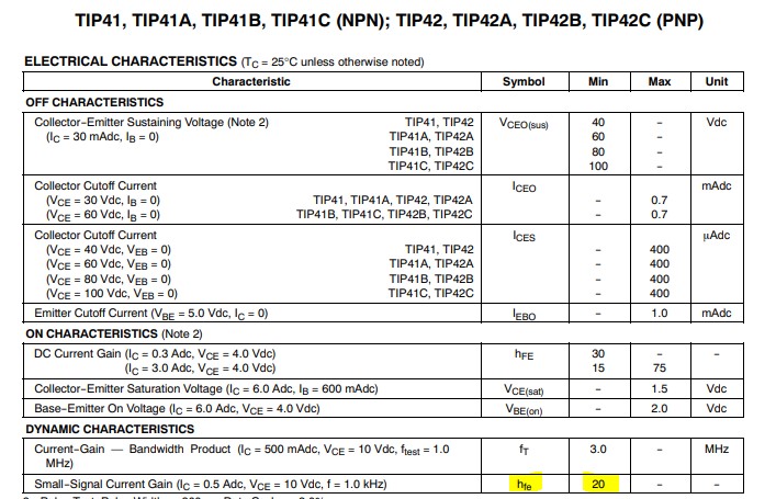
According to the datasheet, the minimum beta for the TIP41 is 20.
IBQ1
$$R_{L}=\frac{Vout}{I_{max}}$$
$$R_{L}=\frac{5V}{100mA}$$
$$R_{L}=50\Omega$$
$$I{RL}=\frac{Vout}{R_{L}}$$
$$I{RL}={5V}{50\Omega}$$
$$I{RL}=100mA$$
$$IE_{Q2}=I_{RL}$$
$$IE_{Q2}=100mA$$
$$IB_{Q2}\approx \frac{IE_{Q2}}{BetaMin_{Q2}}$$
$$IB_{Q2}\approx \frac{100mA}{20}$$
$$IB_{Q2}\approx 5mA$$
$$IE_{Q1}=IB_{Q2}$$
$$IE_{Q1}\approx 5mA$$
$$IB_{Q1}\approx \frac{IE_{Q1}}{Q1Beta_{min}}$$
$$IB_{Q1}\approx \frac{5mA}{90}$$
$$IB_{Q1}\approx 55.556\mu A$$
Note, our output prior to the Darlington Pair was designed for a maximum of 5mA, we decided to increase output load capability to 100mA. This is a current gain or increase of 20. Adding the Darlington pair with a TIP41 power transistor solved two problems. The first was the TIP can handle the increased circuit power and the second the TIP41 with its minimum beta of 20 gave the Darlington a current magnification factor of 20, keeping the base current of Q1 and IZ the same which allows R1 to remain the same.
I assembled and tested the regulator circuit with the Darlington Pair. The circuit was tested both at 20V & 7V inputs with 1KΩ & 50Ω loads. The circuit performed as expected with a regulated output of 5V for each circuit scenario.
This circuit works great however, we should consider the limitations and associated costs. For Q2 any power over two watts will require that the TIP41 have a heat sink. The TIP41 cost itself is just under a dollar. The Zener diode, the fuse, and the fuse holder will add to the overall cost.
Is there a single component that could replace the fuse, fuse holder, Zener diode, and both bipolar junction transistors?
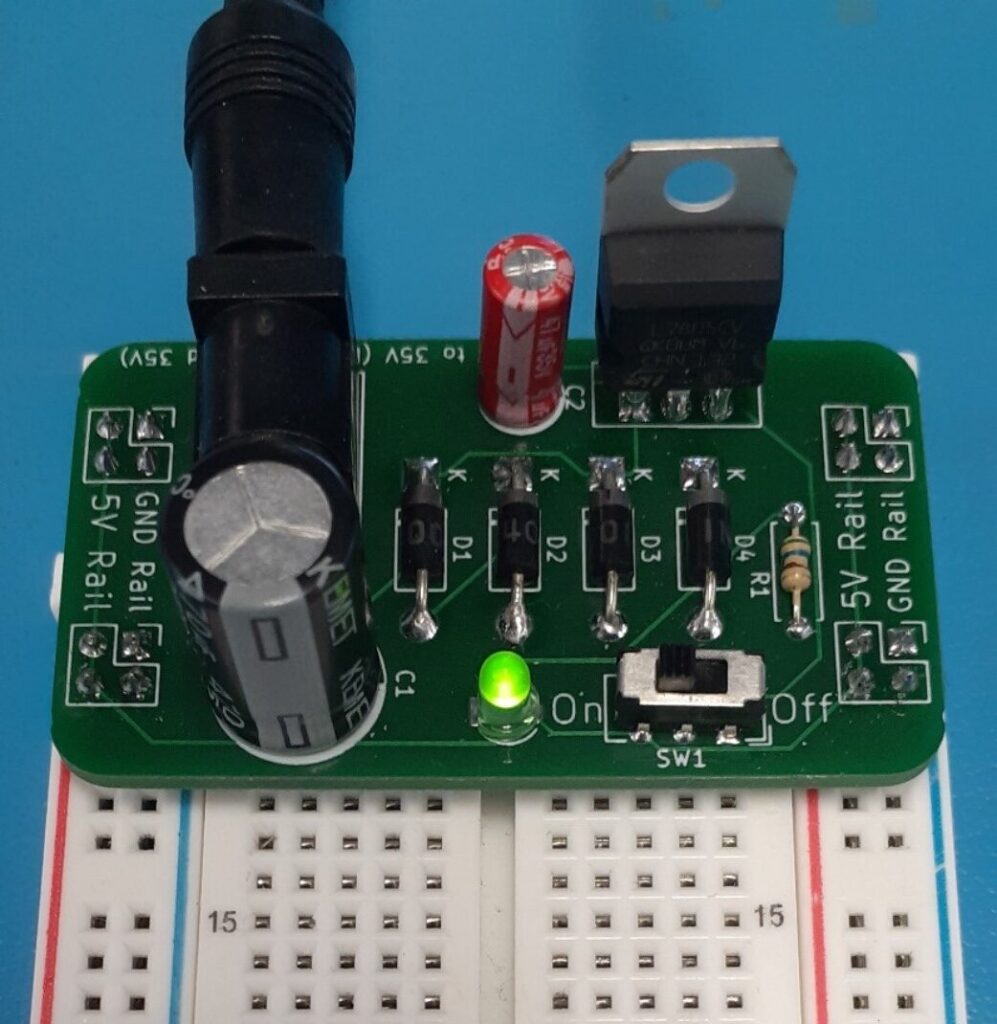
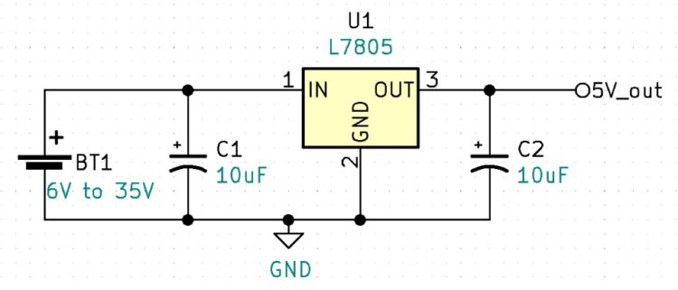
The L7805 Regulator
The L7805 is a 5V fixed linear regulator with internal current limiting and built-in temperature protection. The L7805 is part of the L78 series of linear regulators. The L78 series can be purchased as 5V, 6V, 8V, 8.5V, 9V, 12V, 15V, 18V, and 24V regulators. One point to understand is linear regulators can only regulate down, they cannot regulate up. Therefore, the input voltage will always need to be larger than the regulated output voltage. For the L7805 5V regulator, the input voltage can be a minimum of 6V to an absolute maximum voltage of 35V. At the time of writing this document, I can purchase a single L7805 for $0.62.
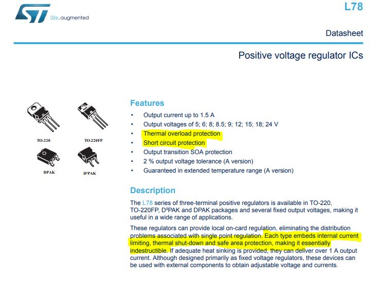
The L7805 has both built-in short circuit protection and over-temperature protection. Meaning if someone accidentally shorts the output, the regulator will not be damaged.
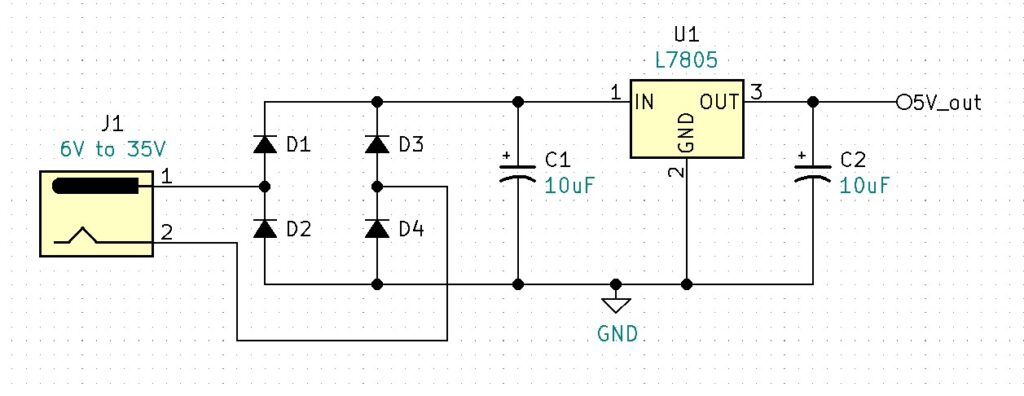
Notice that the circuit fuse has been removed. This is because the L7805 has internal current limiting and over-temperature protection which will provide adequate protection for the circuit. Diodes D1 – D4 provide polarity correction, ensuring that pin1 of the L7805 is always positive.
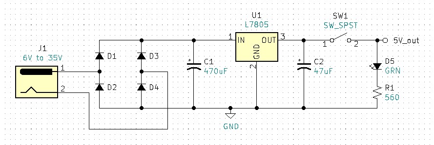
Our final circuit increases the capacitor values for additional filtering. SW1 was added for switchable output voltage. The logical position for this SW1 would have been at the input. However, this project has a small size or form factor, and the micro switch used is rated at 6V, so the problem with putting the switch in series with J1 is that it would be out of specification due to overvoltage. A problem with SW1’s current position is the quiescent current of the L7805. Linear regulators are inefficient when compared to switch-mode power supplies. The inefficiency of the L7805 is due to the fact that the regulator requires a certain amount of current to operate even if there is no load at the output. This would be comparable to the Zener current in the previous circuits. This current is called quiescent current and the typical quiescent current, per the datasheet, for an L7805 is 3.2mA. If you are using a 9V battery and a barrel adapter to power your breadboard power supply circuit you will need to unplug the barrel jack after use to ensure the battery does not drain down. The typical 9V battery is rated at 500mAh, meaning if you run the battery at 500mAs, it will be drained in one hour. So, if our linear regulator requires 3.2mAs and we have no load (no current) at the output, how long will it take to drain the 9V battery?
$$9V_{battery}=\frac{500mA}{1hour}$$
$$L7805Current_{quiescent}=3.2mA$$
$$X_{time}=\frac{1hr\times 500mA}{3.2mA}$$
$$X_{time}=156.25 hours$$
If you leave your 9V battery plugged into the breadboard power supply with no load at the output, you will have a dead battery after 156 hours. I considered not having a switch at all, making the circuit even simpler, and forcing the operator to plug and unplug the barrel jack. However, I like having the ability to switch on and off the 5V GND rails on the breadboard and the goal of this project was to be able to use salvaged barrel jack ACDC wall adapters, not expensive 9V batteries.
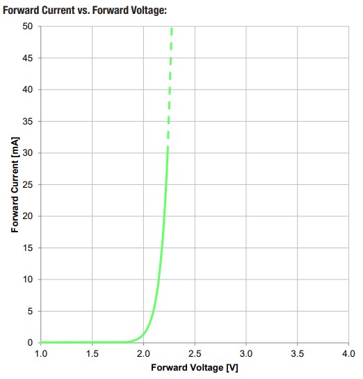
The green LED D5 provides an on/off output indication. The maximum current rating for the LED is 30mA. The forward voltage for this green LED is approximately 2V. This leaves us with 3V across the current limiting resistor R1. What is the minimum resistance that R1 can be without exceeding the diode’s 30mA max current?
$$R1_{min}=\frac{V_{R1}}{Imax_{LED}}$$
$$R1_{min}=\frac{3V}{30mA}$$
$$R1_{min}=100\Omega$$
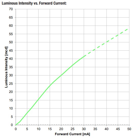
As R1’s resistance value is increased, the LED forward current will decrease, and the LED’s luminous intensity will decrease. Bench testing found that a 560Ω resistor provides a minimum current with adequate LED illumination.