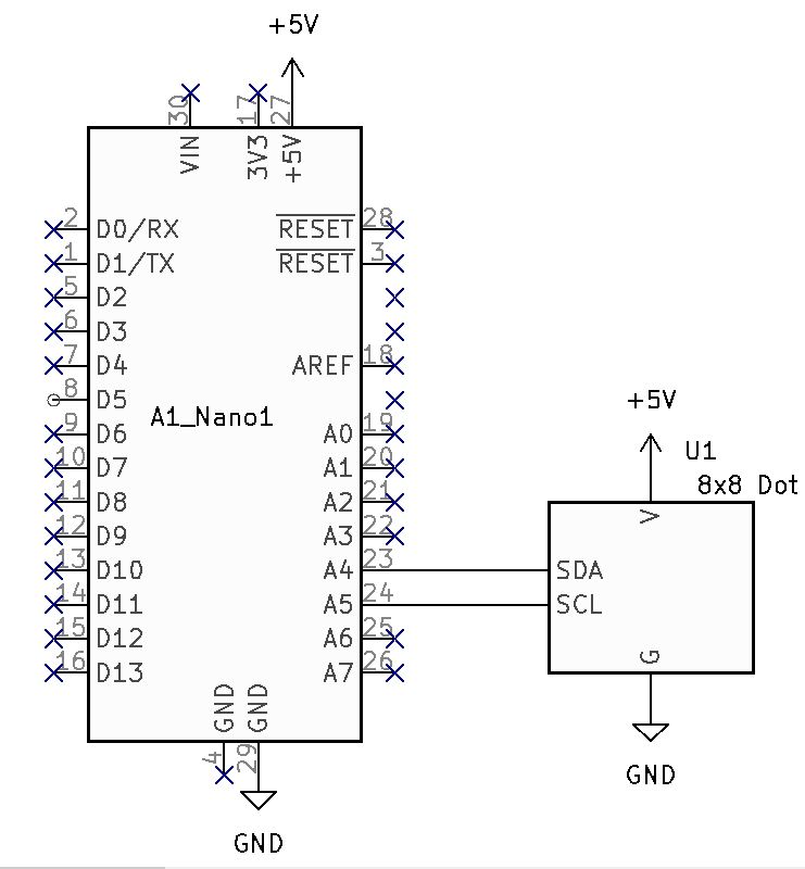
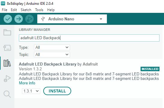
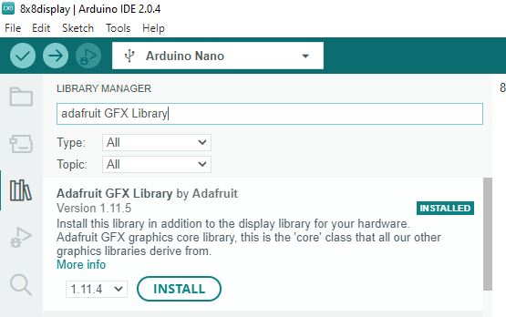
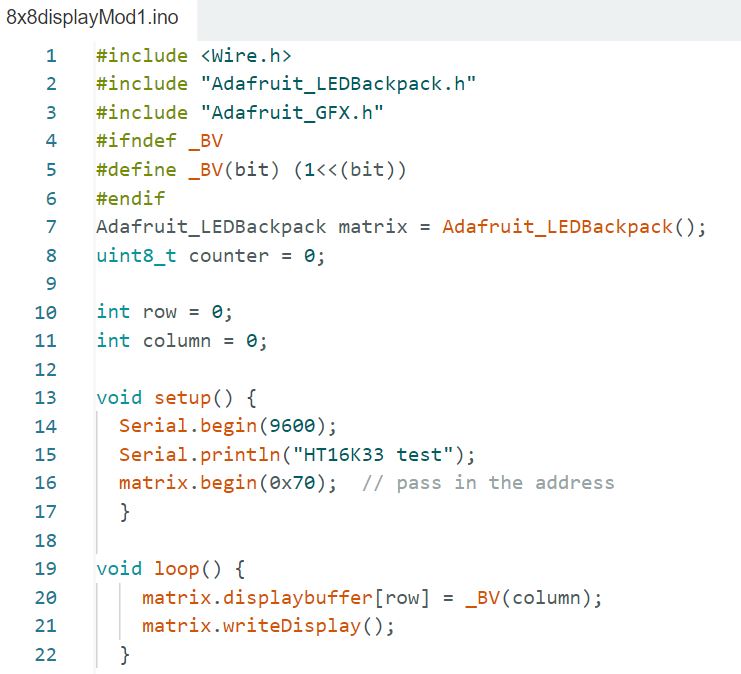
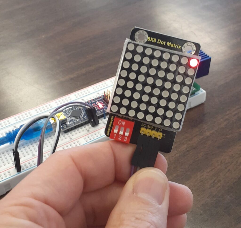
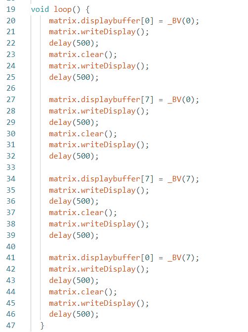
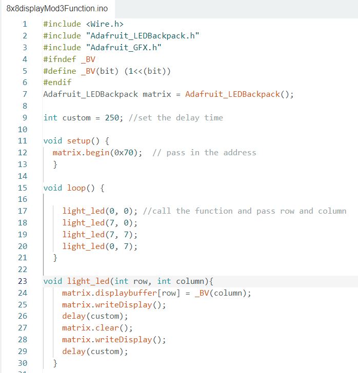
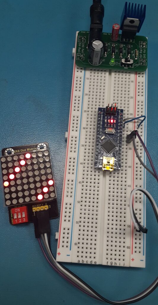
Arduino Nano 8×8 Dot matrix Leave a Comment / Arduino, Electronics / By Tim Leishman This article is included in the ISTEM 2023 Series.Visit the Keyestudio 8×8 wiki page. Arduino Nano 8x8 Dot Matrix schematic Connect the circuit as seen in the above schematic.Install the Adafruit LED Backpack and GFX libraries. Copy, verify, and load the following code.#include <Wire.h> #include "Adafruit_LEDBackpack.h" #include "Adafruit_GFX.h" #ifndef _BV #define _BV(bit) (1<<(bit)) #endif Adafruit_LEDBackpack matrix = Adafruit_LEDBackpack(); uint8_t counter = 0; void setup() { Serial.begin(9600); Serial.println("HT16K33 test"); matrix.begin(0x70); // pass in the address } void loop() { // paint one LED per row. The HT16K33 internal memory looks like // a 8x16 bit matrix (8 rows, 16 columns) for (uint8_t i=0; i<8; i++) { // draw a diagonal row of pixels matrix.displaybuffer[i] = _BV((counter+i) % 16) | _BV((counter+i+8) % 16) ; } // write the changes we just made to the display matrix.writeDisplay(); delay(100); counter++; if (counter >= 16) counter = 0; } Verify Operation.Code Challenge!: Modify the code to light the bottom left corner LED. Code Challenge!: Modify the code to light the upper right LED. Code Challenge!: Modify the code to light the corner LEDs sequentially clockwise. Verify and Load the code.Verify operation.Notice how each chunk of code is similar. Code Challenge!: Simplify the above code by creating a function that will accept two variables for row and column. Code Challenge!: Create additional cool functions. See my code HERE.