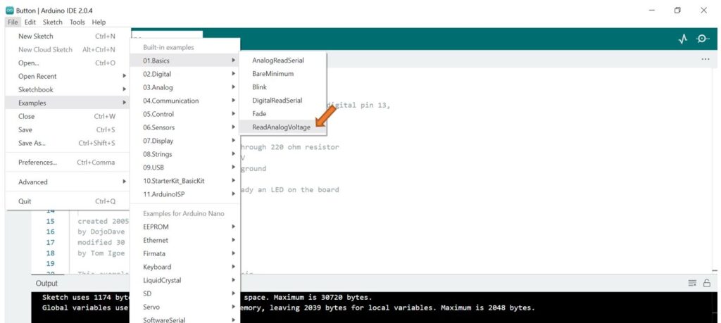
Load the ReadAnalogVoltage sketch into the Arduino Nano.
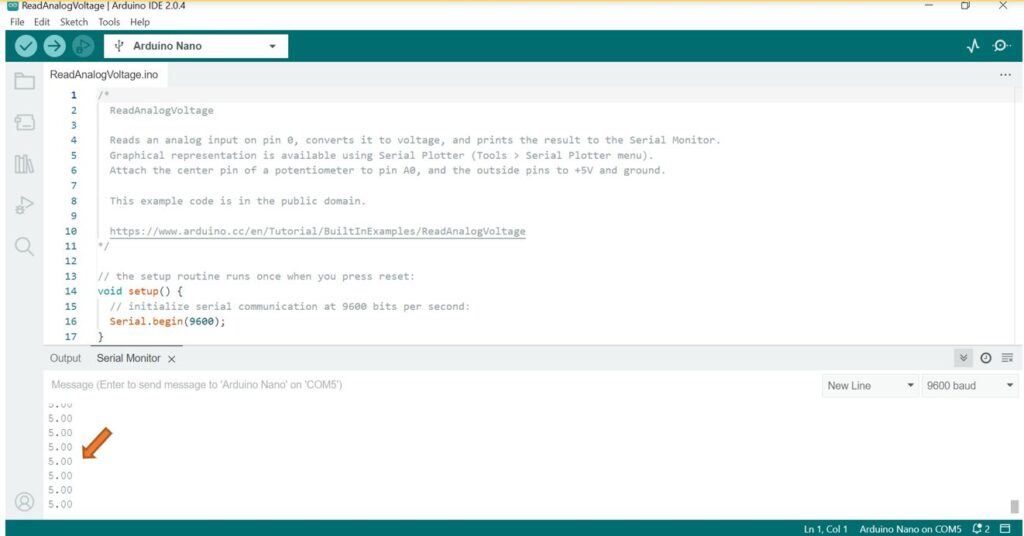
With the Arduino Nano connected to the computer, open the Serial Monitor by clicking the icon in the upper right of the IDE application.
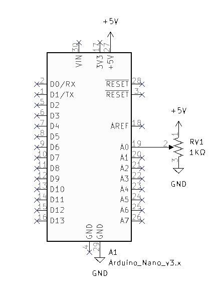
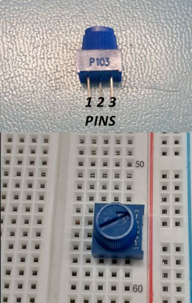
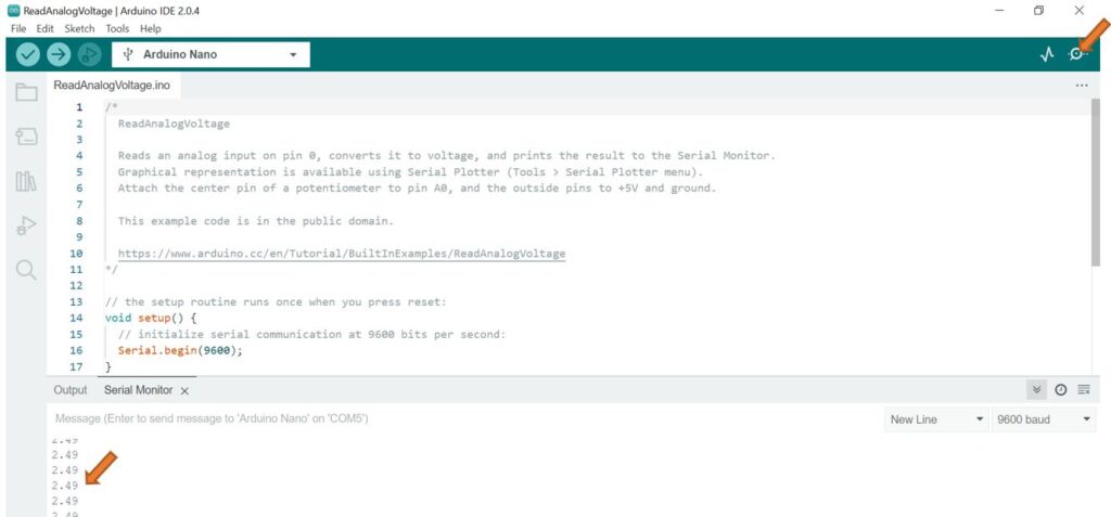
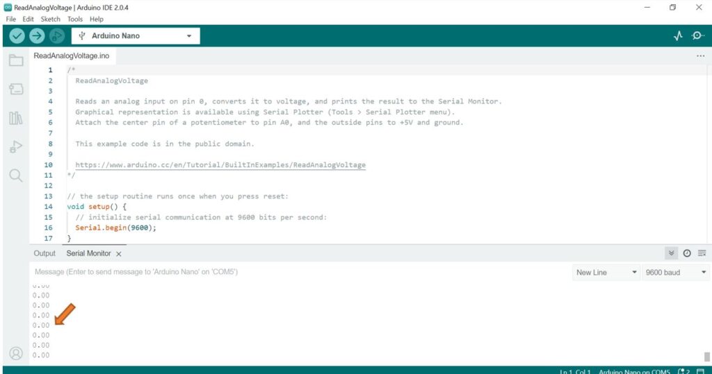
Turn the potentiometer and observe the voltage displayed on the Serial Monitor at the bottom left.
Test the extremes of the potentiometer.
Notice that adjusting the potentiometer from one extreme to the next can display a range of voltage from 0v to 5v.
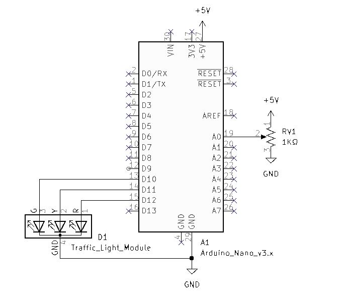
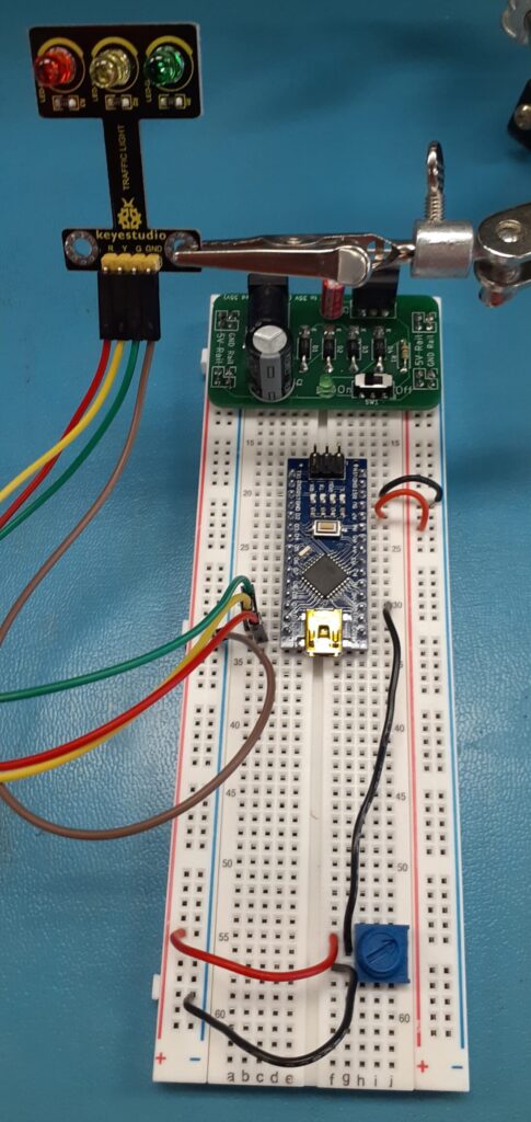
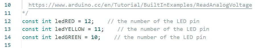
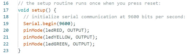
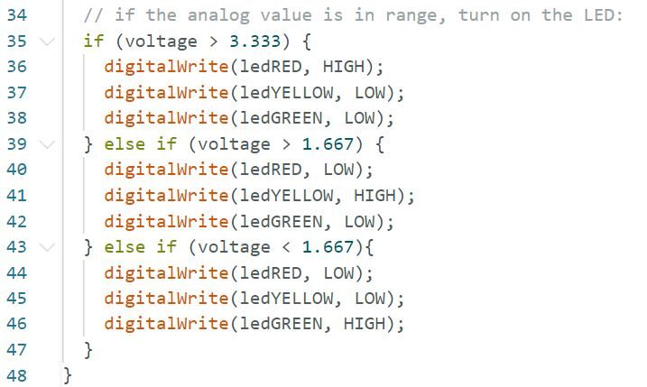
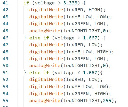
Code Challenge! : Use the “Traffic Light Module” from the sensor kit and modify the code to turn on the Red LED when the voltage is above 3.333v, the Yellow LED from 3.333v to 1.667v, and the Green LED when the voltage is below 1.667v.
Code Modification - If, Else If conditional statements
Code Challenge!: Replace the Potentiometer with the TEMT6000 Ambient Light Sensor.
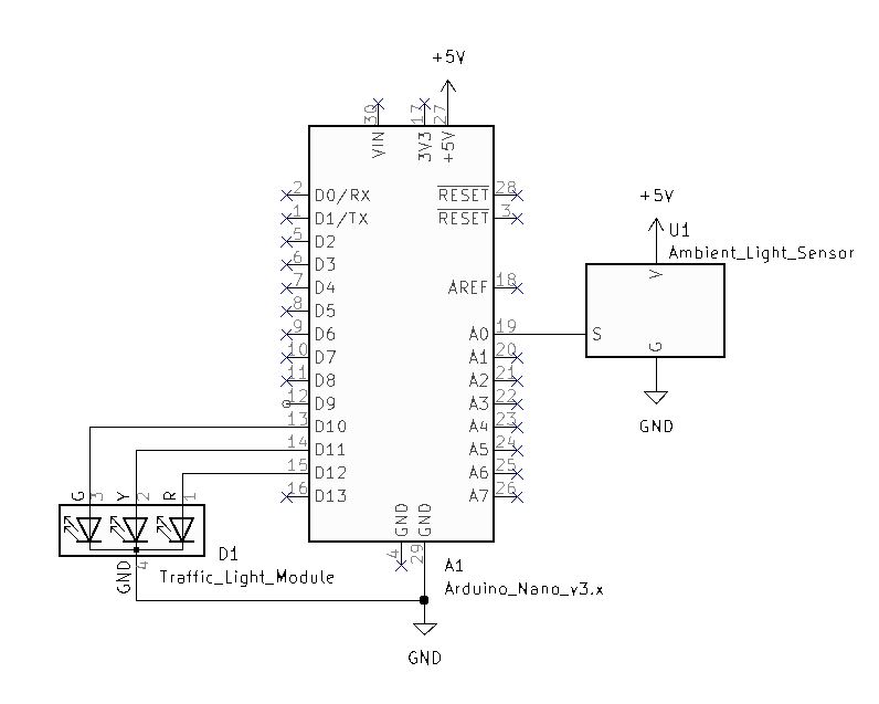
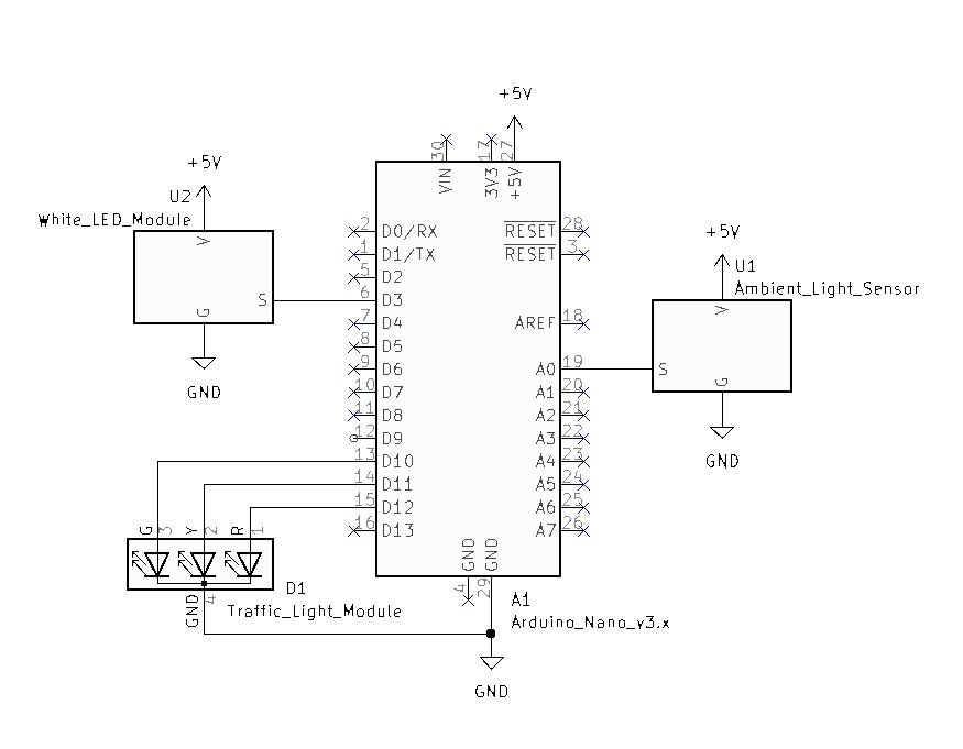
Ambient Light Sensor
Code Modification
Replace the potentiometer with the Ambient Light Sensor.
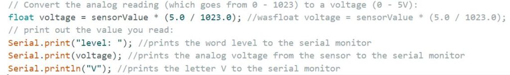
Notice the addition of Serial.print code on either side of the voltage. This will add more readability to the serial monitor.
Check and Upload the code to the Arduino Nano.
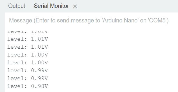
Notice the readability “Level:(analog voltage on pin 19)V
My ambient light sensor is reporting 1.01V to 0.98V range for max light.
Cover the sensor with your hand and observe the change in the output level.
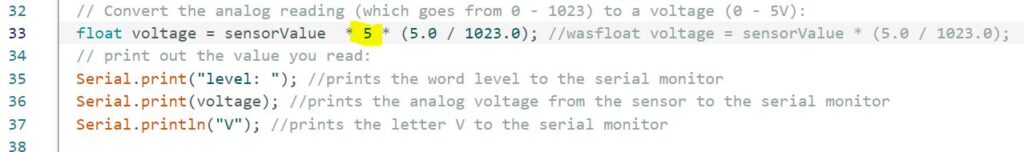
In our current setup 5V represents our maximum and 0V is our minimum value. Because my max ambient is around 1V, we can add a calibration factor of 5 to our sensorValue.
Add your calibration factor to the float voltage sensorValue as seen highlighted in yellow above.
Check and Upload the code.
Verify code by observing the Serial Monitor.
Verify the Traffic Light Sensor operation.
Code Challenge!: Create a Night Light circuit using the Ambient Light Sensor and the White LED Module.
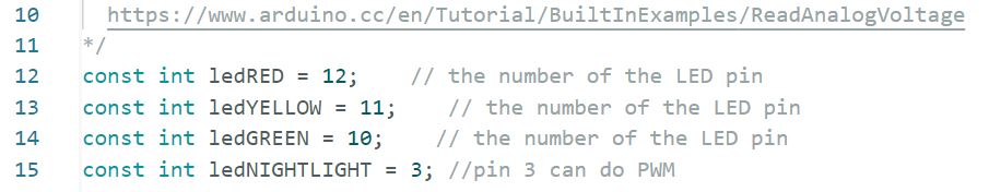
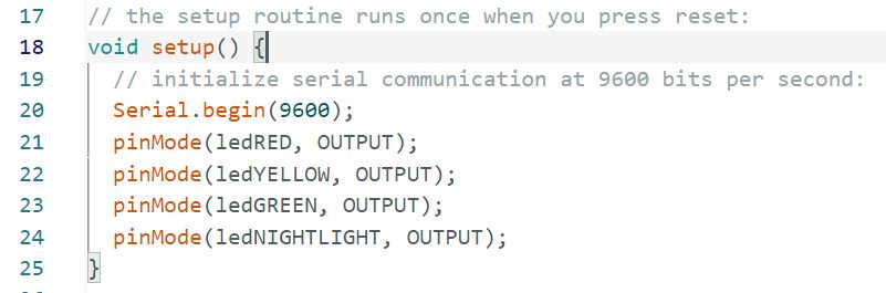
Make ledNIGHTLIGHT equal to pin 3
Make pin 3 an output.
Add your conditions.
Because we are using an analogWrite (8bit) we can range the output from 0-255 which represents 0V to 5v.