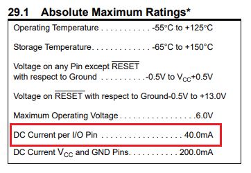
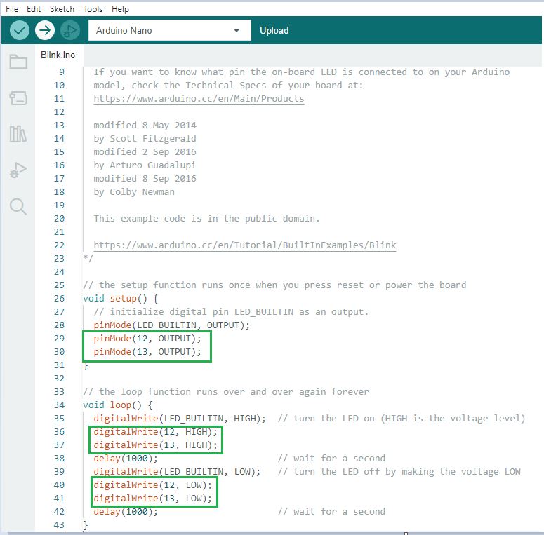
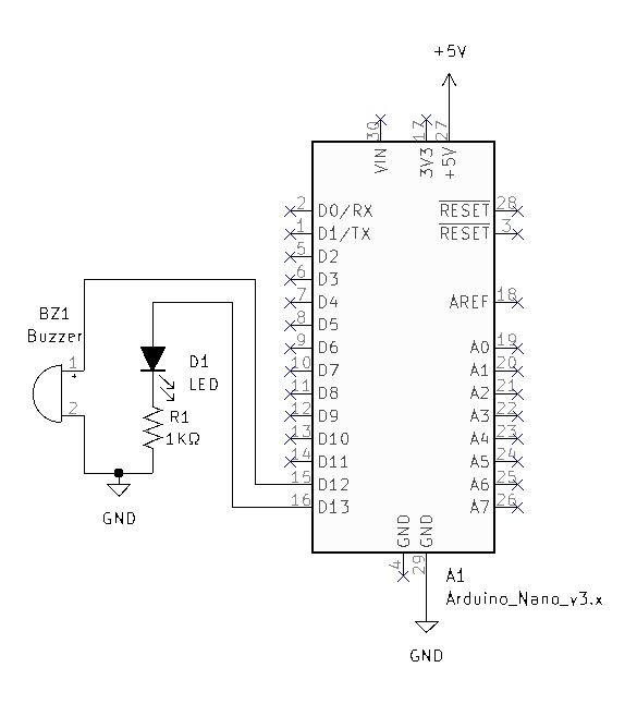
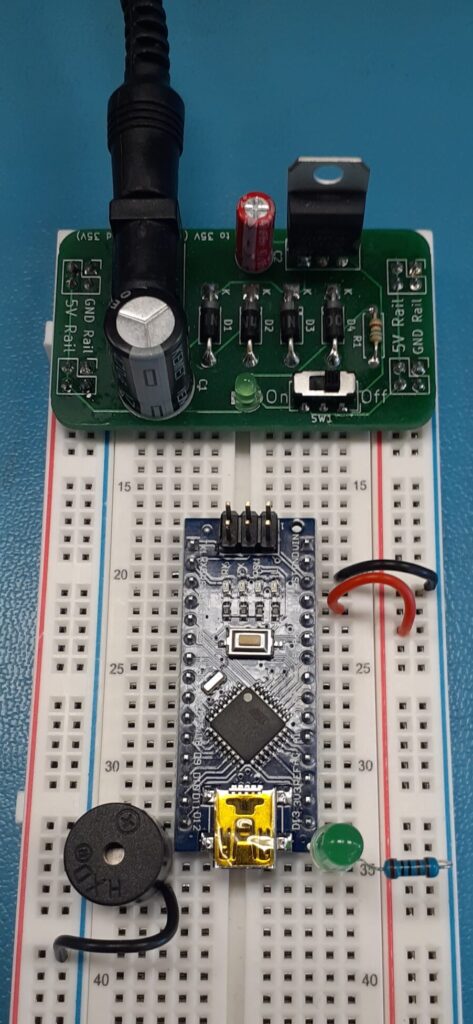
Arduino Nano, IDE Program and Circuit Integration Leave a Comment / Arduino, Electronics, Programming / By Tim Leishman This article is included in the ISTEM 2023 SeriesDisconnect the breadboard PS from the wall power adapter.Install the Arduino Nano onto the breadboard. The Arduino Nano uses the Atmega 328p microcontroller.The absolute maximum current that the I/O pins can drive is listed as 40mA in the datasheet. Using the Nano, we can safely drive our previously designed LED circuit at 3mA and the Buzzer circuit at 25mA. Review the circuit designs here. Open the Blink program in the Arduino IDE – instructions here Introduction to Programming Arduino. Modify the Blink program by adding the above lines of code boxed in green. Verify the code by clicking the checkmark in the upper left.Upload the code to the Nano by clicking the upload arrow in the upper left. Disconnect the computer from the Nano and with the power off assemble the above circuit. Turn on the Breadboard Power Supply to test the circuit. Unmute the video to hear the buzzer.