This article is included in the ISTEM 2023 Series
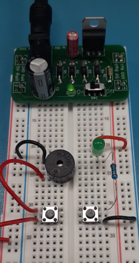
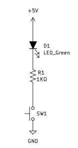
Let’s use our Breadboard PS to light an LED (light emitting diode). First, we can determine the LED voltage needed to light a general-purpose Green LED by looking at a data sheet.
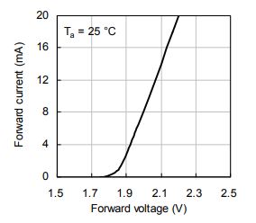
Observing the characteristic curve of forward voltage vs forward current. We can see that this LED will drop around 2V with an approximate minimum forward current of 3mA.
Knowing the Breadboard power supply produces a regulated 5V and the LED will require 2V, the addition of a current limiting resistor is required.
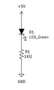
R1 will drop the remaining voltage and provide current limiting for the LED. Ohm’s law states that Resistance is equal to Voltage divided by Current. We can find the VR1 by subtracting the LED voltage from the power supply voltage.
$$R1=\frac{V}{I}$$
We can find the VR1 by subtracting the LED voltage from the power supply voltage.
$$V_{R1}=V_{BBPS}-V_{LED}$$
$$V_{R1}=5V-2V$$
$$V_{R1}=3V$$
I is equal to the desired forward LED current.
$$I=3mA$$
$$R1=\frac{V}{I}$$
$$R1=\frac{3V}{3mA}$$
$$R1=1K\Omega$$
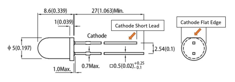
The LED will correctly operate with forward current with the anode more positive with respect to the cathode. The LED cathode can be physically identified as having a shorter lead than the anode. Additionally, typically there will be a flat edge at the base of the LED, the lead closest to the flat edge will be the cathode.

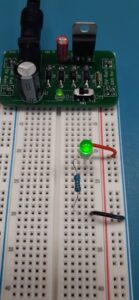
With the DMM set to VDC, measure the voltage across the LED and the voltage across the resistor.
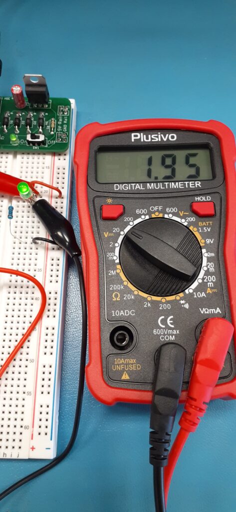
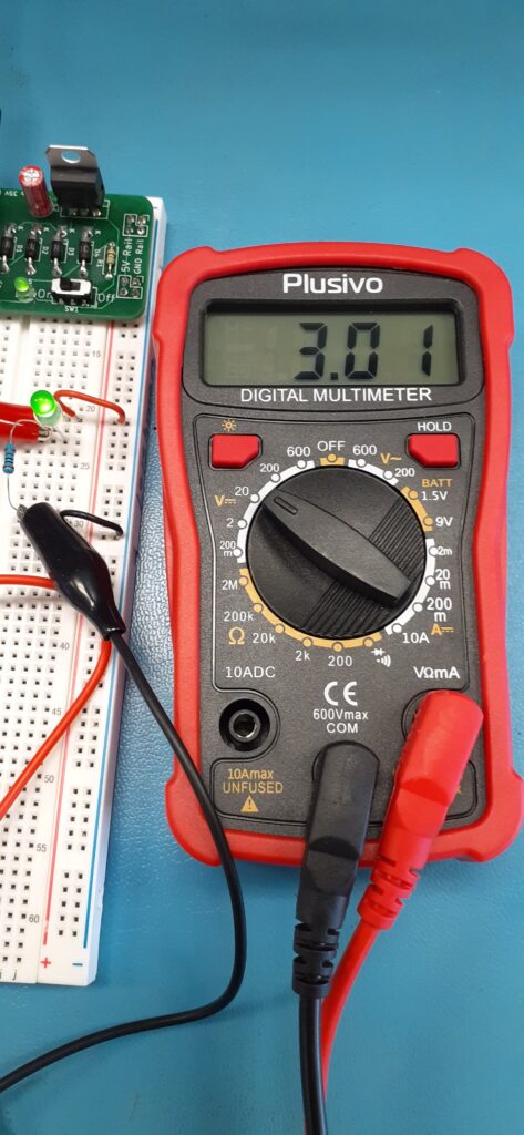
Add a momentary push switch to the circuit.
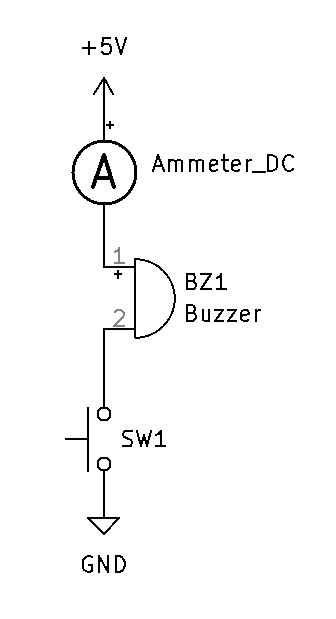
Construct the Piezo Circuit and measure the current. I measured 25mA when the piezo is activated. Unmute the video if you want to hear what the piezo BZ1 sounds like.
