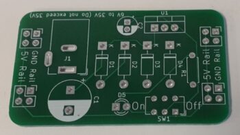
Start by soldering diodes D1-D4. Make sure the orientation of the diodes is correct. The silver band is the cathode and will go toward the K mark on the PCB.
PCB with Polarity Correction Diodes
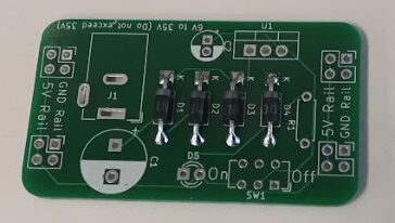
The orientation of R1 is not important. D5 the LED must be soldered with the proper orientation. There is a flat side on the collar of the LED, this flat side should be associated with the short lead. The short lead and flat side collar should be soldered to the square pad. The long lead of the LED goes to the round pad, toward SW1.
PCB with LED and R1
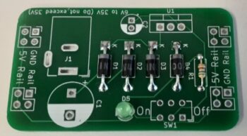
The electrolytic capacitors are polarity sensitive and must be installed correctly. Solder the negative pins to the round pad with the white and the positive pin to the square pad. Solder switch SW1 into place, orientation is not an issue for the switch.
PCB with Capacitors and Switch
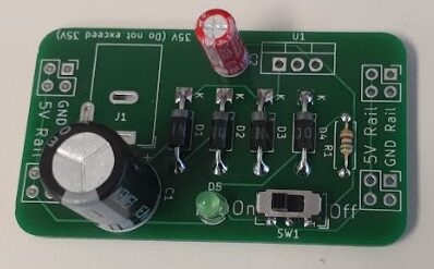
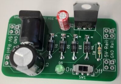
The barrel plug input adapter has kinked pins. At first this part can be a little difficult to get into position. Make sure to align the pins and then press hard and it should snap into place. Orient the L7805 as seen in the picture, front to the circuit and back to open space.
PCB with Barrel Jack and L7805
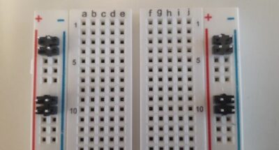
Snap off the header pins in 2×2 groups. The easiest way to do this is to use two needle nose plyers. On the breadboard, there are five pin groups going down the power rails. Orientate the header pins as seen in the picture in the first slots of two adjoining five-pin groups. Notice the snap-off tabs are all oriented in the same direction.
Header Pin Alignment with Breadboard
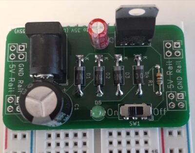
Place the PCB on the header pins and press firmly to make sure all the header pins are square and flush with the breadboard. Solder the header pins in place, from the top of the PCB.
PCB Header Pin Alignment with Breadboard
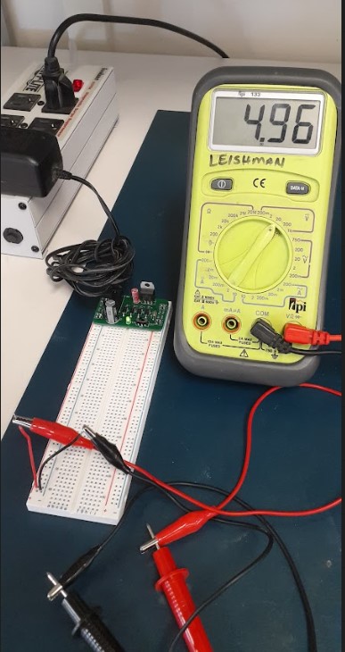
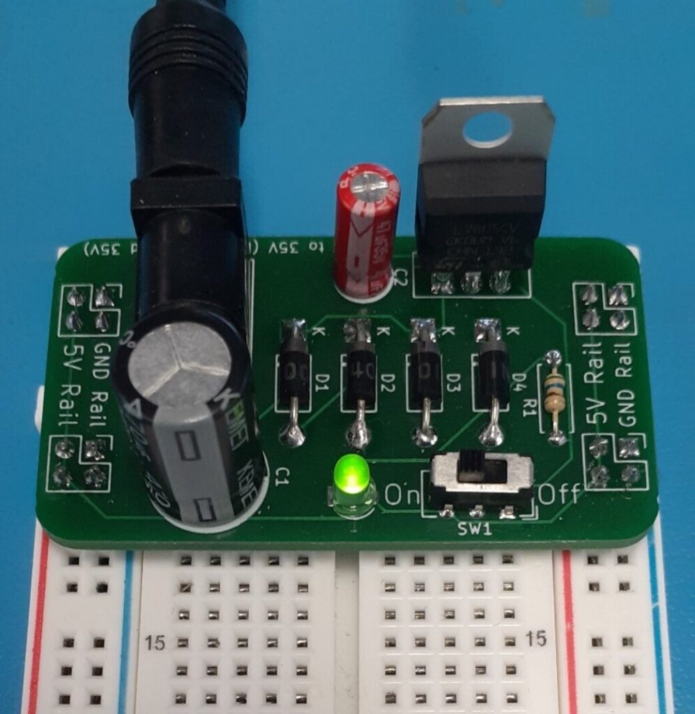
After soldering the header pins, the Breadboard Power Supply is complete. Plug in your ACDC wall adapter. Test that the green led turns on and off with SW1 and verify that both power rails have 5VDC.
Final Test
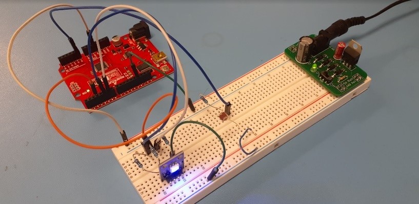
Breadboard Power Supply powering an Arduino project
I hope you enjoyed this lesson on linear regulated power supplies. Now put your power supply knowledge to work and develop lots of cool electronic projects.
If you are a Middle School or High School STEM teacher please connect with me and consider purchasing the Breadboard Power Supply kits from the Idaho State University Electronics Club. The proceeds earned from the Breadboard Power Supply kits will help support our Skills USA competition and other club events. Please contact me at [email protected].