Previous Article in this series
The prerequisite for this article can be read here:
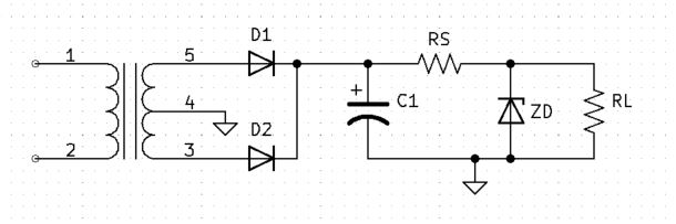
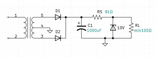
The Problem with Unregulated Power Supplies
Given
Given: Vpri = 120v 60Hz, Turns ratio = 4:1, VZ=10V, C1 = ?, RS=?, RL = ?
Review the calculations for the Full-wave Center Tapped circuit
Getting started
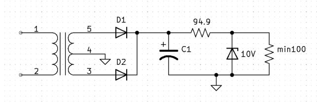
Zener Data Sheet
1N5925B
$$IZK=0.25mA$$
$$IZM=150mA$$
The 1N5925B is a 10V zener. IZK or the knee current is the minimum current required to maintain zener regulation. IZM is the maximum current that the zener can safely handle. For the 1N5925B, IZK is 0.25mA and IZM is 150mA. For design purposes we will keep the zener current 10% above the knee current and 10% below IZM. This makes our acceptable zener current 0.275mA to 135mA. Sometimes zener diode data sheets do not list IZM, zener power will be specified and IZM can be calculated from the given power.
$$IZM=\frac{1.5W}{10V}$$
$$IZM=150mA$$
For design purposes:
$$IZ_{min}=0.275mA$$
$$IZ_{max}=135mA$$
RS calculations with no load resistor
Imagine the filter capacitor voltage waveform without the load resistor RL. All the circuit current that flows through RS will also flow through the zener diode. Now, we know that we want our max zener current is 135mA. .
$$VRS_{max}=VC_{max}-VZ$$
$$VRS_{max}=20.516V-10V$$
$$VRS_{max}=10.516V$$
$$RS_{min}=\frac{VRS_{max}}{IZ_{max}}$$
$$RS_{min}=\frac{10.516V}{135mA}$$
$$RS_{min}=77.896\Omega$$
$$RS_{max}=\frac{VRS_{max}}{IZ_{min}}$$
$$RS_{max}=\frac{10.516V}{0.275mA}$$
$$RS_{max}=38.251K\Omega$$
Problems
Determine max output current
VCmin
Let’s say there is a 2-vpp ripple at the capacitor.
$$VC_{min}=Vc_{max}-2v$$
$$VC_{min}= 20.516v-2v$$
$$VC_{min}=18.516v$$
VRSmin
$$VRS_{min}=18.516V-10V$$
$$VRS_{min}=8.516V$$
IRSmax at VRSmin
$$IRS_{max}=\frac{8.516V}{77.896\Omega}$$
$$IRS_{max}=109.325mA$$
IRLmax with RS=77.896 ohms
$$IRL_{max}=IRS_{max}-IZ_{min}$$
$$IRL_{max}=109.325mA-0.275mA$$
$$IRL_{max}=109.05mA$$
Redesigning for 100mA and improved RS value with Vc ripple voltage equal to 1vpp
new VCmin
Designing for 1-vpp ripple at the capacitor.
$$VC_{min}=Vc_{max}-1v$$
$$VC_{min}= 20.516v-1v$$
$$VC_{min}=19.516v$$
new VRSmin
$$VRS_{min}=19.516V-10V$$
$$VRS_{min}=9.516V$$
new IRSmax at VRSmin
$$IRS_{max}=\frac{9.516V}{77.896\Omega}$$
$$IRS_{max}=122.163mA$$
new IRLmax with RS=77.896 ohms
$$IRL_{max}=IRS_{max}-IZ_{min}$$
$$IRL_{max}=122.163mA-0.275mA$$
$$IRL_{max}=121.888mA$$
RS with IRLmax = 100mA
$$VRS_{min}=9.516V$$
$$RS=\frac{VRS_{min}}{IRS}$$
$$RS=\frac{9.516V}{100.275mA}$$
$$RS=94.9\Omega$$
RLmin
$$RLmin=\frac{Vz}{IRLmax}$$
$$RLmin=\frac{10V}{100mA}$$
$$RLmin=100\Omega$$
C1
Calculate C1 at max current. In a max current scenario, RL will equal 100 ohms and IZ will be at its minimum.
$$RZ=\frac{VZ}{IZ}$$
$$RZ=\frac{10V}{0.275mA}$$
$$RZ=36.36K\Omega$$
$$Req=RZ//RLmin$$
$$Req=36.36K//100$$
Because 36.35K is will over 10X larger than 100, our equivalent parallel resistance will be equal to 100 ohms.
$$Req=100\Omega$$
$$Rth_{C}=RS+Req$$
$$Rth_{C}=94.9 ohms + 100 ohms$$
$$Rth_{C}=194.9 ohms $$
Next, factor in the 1vpp ripple to determine C:
$$VC=Vfin-(Vfin-Vin)e^\frac{-t}{RC}$$
$$19.516v=0-(0-20.516V)e^\frac{-8.333mS}{194.9\Omega \times C}$$
$$19.516v=(20.516V)e^\frac{-8.333mS}{194.9\Omega \times C}$$
$$\frac{19.516v}{20.516v}=e^\frac{-8.333mS}{194.9\Omega \times C}$$
$$LN\frac{19.516v}{20.516v}=\frac{-8.333mS}{194.9\Omega \times C}$$
$$-0.04997=\frac{-8.333mS}{194.9\Omega \times C}$$
$$C=\frac{-8.333mS}{194.9\Omega \times -0.04997}$$
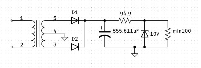
$$C=855.611uF$$
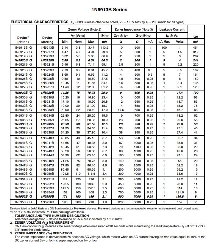
Design circuit with Standard Values
For practical design, round the capacitor value up to a standard value and round RS down to the next standard value.
Round C1 from 855.611uF to 1000uF and RS from 94.9 ohms to 91 ohms.
Final Circuit Calculations:
No Load Scenario
Imagine someone has removed the load.
$$RL=\infty$$
$$IZ_{max-no load}=\frac{VC_{max}-VZ}{RS}$$
$$IZ_{max- no load}=\frac{20.516V-10V}{91\Omega}$$
$$IZ_{max-no load}=115.56mA$$ Our IZ of 115.56mA with no load is less than the IZM specification of 150mA, which is good!
IZmin with 100 ohm load final circuit
$$VC_{min}=Vfin-(Vfin-Vin)e^\frac{-t}{RC}$$
$$VC_{min}=0-(0-20.516V)e^\frac{-8.333ms}{(91\Omega+100)\Omega\times1000uF}$$
$$VC_{min}=19.640V$$
$$VRS_{min}=VC_{min}-VZ$$
$$VRS_{min}=19.640V-10V$$
$$VRS_{min}=9.640V$$
$$IRS_{min}=\frac{VRS_{min}}{RS}$$
$$IRS_{min}=\frac{9.640V}{91\Omega}$$
$$IRS_{min}=105.936mA$$
$$IRL=\frac{VZ}{RL}$$
$$IRL=\frac{10V}{100\Omega}$$
$$IRL=100mA$$
$$IZ=IRS-IRL$$
$$IZ=105.936mA-100mA$$
$$IZ_{100mA load}=5.936mA$$ Our IZ of 5.936mA with an load resistor RL equal to 100 ohms is less than the IZK specification of 0.25mA, which is good!
VC Waveform
Vout waveform
Improvements over un-regulated circuits
Notice that there is no ripple at the output. And the DC voltage will remain at 10VDC as the load is varied from 0mA to 100mA. This is an improvement over our previous un-regulated power supplies.
Problem with Zener Regulation
Observe that regardless of the load, the zener regulated circuit uses the same amount of current. The current at RS is always the same regardless of the load.
$$IRS=IZ+IRL$$
If the load is small, the excess current is diverted through the zener to reference, this is inefficient. In a no load situation all of IRS will flow through the zener, totally inefficient. This also dictates our maximum current because IRS can never be larger than the maximum zener current.
$$IRS_{max}=IZM$$
Additionally, the maximum load current is also dependent on the zener maximum current.
$$IRL_{max}=IZM-IZK$$
We can improve efficiency and maximum load current using transistor regulation.