Unregulated Bridge Rectification, Pi Filtered

Previous Article in this series

The prerequisite for this article can be read here: Unregulated Fullwave Bridge Rectifier with Filtering

Given

Given: Vpri = 120v & 60Hz, Turns ratio = 4:1, C1 = 10uF, C2=20uF, RS=500ohms, & RL = 10K Ohms

Calculate Primary Voltage

Start by converting the primary RMS voltage to Peak voltage.
$$Vpeak_{Primary}=\frac{V_{RMS}}{0.707}$$
$$Vpeak_{Primary}=\frac{120V_{RMS}}{0.707}$$
$$Vpeak_{Primary}=169.731vp$$
 

Primary Peak to Peak Voltage Waveform

Calculate Secondary Voltage

Find the Secondary Peak Voltage.

$$Vpeak_{Secondary}=\frac{Vpeak_{Primary}}{turns-ratio}$$
$$Vpeak_{Secondary}=\frac{169.731vp}{4}$$
$$Vpeak_{Secondary}=42.433vp$$


Secondary Voltage Waveform

Find Unfiltered Output Voltage

Imagine the circuit without the filter capacitor. 

During the positive cycle diodes, D2 and D4 will be forward-biased allowing current to flow to the output. 

During the positive cycle diodes, D1 and D3 will be forward-biased allowing current to flow to the output. 

$$Vout_{PositiveCycle}=VSecondary_{PositiveCycle}-2Vdiode$$
$$Vout_{PositiveCycle}=42.433vp-1.4V$$
$$Vout_{PositiveCycle}=41.033vp$$
$$Vout_{NegativeCycle}=41.033vp$$
 

Unfiltered Output Waveform Voltage 120hz

Point A, Add C1 Filtering

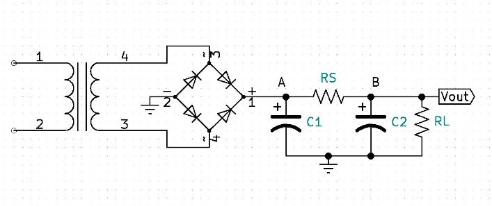
Capacitor C1 will immediately charge to 41.033V (Vsecondary – 2Vdiode).  During the valley of the waveform, the capacitor will have one cycle worth of time to discharge,  this is a full-wave rectifier, the time will be 1/120hz or8.333ms. C2 will look like an open to C1. C1’s discharge path is through RS and RL. Because we are looking for a discharge voltage, Vfinal will be equal to zero volts in our formula and Vinitial will be equal to 41.033V. 

$$VC_{maxPointA}=41.033V$$

$$VC_{minPointA}=Vfinal-((Vfinal-Vinitial)e\frac{-time}{(RS+RL)C})$$
$$VC_{minPointA}=0-((0-41.033)e\frac{-8.333mS}{10.5Kx10uF})$$
$$VC_{minPointA}=37.902vp$$
 

Point A, Filtered Output Waveform Voltage 120hz

Point A, Vrpp & VDC

V ripple peak to peak is found by subtracting Vmax from Vmin & VDC is the average voltage.

$$Vrpp = Vmax-Vmin$$
$$Vrpp= 41.033vp-37.902vp$$
$$Vrpp=3.1307vpp$$
$$VDC=\frac{Vmax+Vmin}{2}$$
$$VDC=\frac{41.033V+37.902}{2}$$
$$VDC=39.4675V$$
 

Point A, VDC Waveform Voltage represented in blue

Point B

Now that we know what is happening at point A, we can solve for the waveform voltages at point B. Because the AC ripple will be superimposed on the DC we can simply analyze the circuit both as a DC circuit and then as an AC circuit and our output waveform will be the analysis of both superimposed. 

Point B, DC analysis

Capacitors will look like an open to DC. Therefore, the circuit redraw for DC will look like the following. 

Point B, DC Calculations

$$VDC_{B}=\frac{VDC_{A}}{RS+RL}\times RL$$
$$VDC_{B}=\frac{39.4675}{500+10K}\times 10K$$
$$VDC_{B}=37.588V$$

Point B, AC analysis

Find the approximate capacitive reactance of C2 at 120hz.

$$XC_{C2}=\frac{1}{2\pi F C}$$

$$XC_{C2}=\frac{1}{2\pi\times120hz\times20uF}$$

$$XC_{C2}=66.315\Omega$$
 
Because C2 is in parallel with RL and XC2 is over one hundred times smaller than RL, the equivalent resistance will be equal to XC2. 
 

Equivalent AC circuit

AC Out Calculations

Impedance Calculations
$$zt=\sqrt{r^2 + xc^2}$$
$$zt=\sqrt{500^2 + 66.315^2}$$
$$zt=504.379\Omega$$
 
Current Calculations
$$itotal_{PP}=\frac{vrpp}{zt}$$
$$itotal_{PP}=\frac{3.1307vpp}{504.379\Omega}$$
$$itotal_{PP}=6.207mApp$$
 
Vout ripple calculations
$$vrpp=xc\times itotal$$
$$vrpp=66.315\Omega\times 6.207mApp$$
$$vrpp=411.62mVpp$$
 

Superimposed AC & DC

Knowing that our output DC is 37.588V and our AC ripple out is 411.62mVpp, we can now superimpose and find our voutmaxp and voutminp voltages. 

Find ripple peak voltage
$$vrp=\frac{vrpp}{2}$$
$$vrp=\frac{411.62mvpp}{2}$$
$$vrp=205.81mvp$$
 
Find Vmax and Vmin output voltages
The output waveform will vary above and below the output DC level by the ripple peak voltage. 
 
$$vmaxp=VDC+vrp$$
$$vmaxp=37.588V + 205.81mVp$$
$$vmaxp=37.794vp$$
 
$$vminp=VDC-vrp$$
$$minp=37.588V – 205.81mVp$$
$$vminp=37.382vp$$
 

Output Superimposed AC/DC waveform

Vrms & %ripple

Vrms is the RMS equivalent of the ripple voltage and %ripple is a ratio of Vrms to VDC, describing how well the output DC is filtered. 

Notice that the ripple waveform is more triangular than sinusoidal. This is why we use the square root of 3 rather than 2.

$$Vrms=\frac{Vrpp}{2\sqrt{3}}$$
 
$$Vrms=\frac{411.62mVpp}{2\sqrt{3}}$$
 
$$Vrms=118.82mV$$
 
$$\%ripple=\frac{Vrms}{VDC}\times100$$
 
$$\%ripple=\frac{118.82mV}{37.588V}\times100$$
 
$$\%ripple=0.316\%$$

Leave a Comment

Your email address will not be published. Required fields are marked *